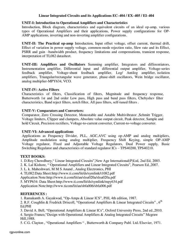
Operational Amplifier By Ramakant Gaikwad Pdf Creator

Ramakant gaikwad operational amplifiers pdf Jain.Feb 20, 2012. Op amp ramakant gaikwad pdf download 1 Ramakant A.Gayakwad, Op-Amps and linear integrated Circuits.OP-AMPS AND LINEAR INTEGRATED CIRCUITS: LAB SOLUTIONS MANUAL BY RAMAKANT A.GAYAKWAD.January 14, 2012. Ramakant gayakwad op amp pdf.
A μA741 integrated circuit, one of the most successful operational amplifiers Type Invented First production 1967 Pin configuration • V+: non-inverting input • V−: inverting input • Vout: output • VS+: positive power supply • VS−: negative power supply The power supply pins ( V S+ and V S−) can be labeled in different ways ( See ). Often these pins are left out of the diagram for clarity, and the power configuration is described or assumed from the circuit. Circuit diagram symbol for an op-amp. Pins are labeled as listed above. An operational amplifier (often op-amp or opamp) is a high- electronic voltage with a and, usually, a output. In this configuration, an op-amp produces an output potential (relative to circuit ground) that is typically hundreds of thousands of times larger than the potential difference between its input terminals. Operational amplifiers had their origins in, where they were used to perform mathematical operations in many linear, non-linear, and frequency-dependent circuits.
The popularity of the op-amp as a building block in is due to its versatility. By using, the characteristics of an op-amp circuit, its gain, input and, etc. Are determined by external components and have little dependence on or in the op-amp itself.
Op-amps are among the most widely used electronic devices today, being used in a vast array of consumer, industrial, and scientific devices. Many standard IC op-amps cost only a few cents in moderate production volume; however, some integrated or hybrid operational amplifiers with special performance specifications may cost over 100 in small quantities. Op-amps may be packaged as components or used as elements of more complex integrated circuits.
The op-amp is one type of. Other types of differential amplifier include the (similar to the op-amp, but with two outputs), the (usually built from three op-amps), the (similar to the instrumentation amplifier, but with tolerance to that would destroy an ordinary op-amp), and (usually built from one or more op-amps and a resistive feedback network). • In a closed loop the output attempts to do whatever is necessary to make the voltage difference between the inputs zero. • The inputs draw no current.: 177 The first rule only applies in the usual case where the op-amp is used in a closed-loop design (negative feedback, where there is a signal path of some sort feeding back from the output to the inverting input). These rules are commonly used as a good first approximation for analyzing or designing op-amp circuits.: 177 None of these ideals can be perfectly realized. A real op-amp may be modeled with non-infinite or non-zero parameters using equivalent resistors and capacitors in the op-amp model.
The designer can then include these effects into the overall performance of the final circuit. Some parameters may turn out to have negligible effect on the final design while others represent actual limitations of the final performance that must be evaluated. Real op-amps [ ] Real op-amps differ from the ideal model in various aspects. DC imperfections [ ] Real operational amplifiers suffer from several non-ideal effects: Finite gain is infinite in the ideal operational amplifier but finite in real operational amplifiers. Typical devices exhibit open-loop DC gain ranging from 100,000 to over 1 million.
So long as the (i.e., the product of open-loop and feedback gains) is very large, the circuit gain will be determined entirely by the amount of negative feedback (i.e., it will be independent of open-loop gain). In cases where must be very high, the feedback gain will be very low, and the low feedback gain causes low loop gain; in these cases, the operational amplifier will cease to behave ideally. Finite The differential input impedance of the operational amplifier is defined as the impedance between its two inputs; the common-mode input impedance is the impedance from each input to ground. -input operational amplifiers often have protection circuits that effectively short circuit any input differences greater than a small threshold, so the input impedance can appear to be very low in some tests. However, as long as these operational amplifiers are used in a typical high-gain negative feedback application, these protection circuits will be inactive.
The input bias and leakage currents described below are a more important design parameter for typical operational amplifier applications. Non-zero Low output impedance is important for low-impedance loads; for these loads, the voltage drop across the output impedance effectively reduces the open loop gain. In configurations with a voltage-sensing negative feedback, the output impedance of the amplifier is effectively lowered; thus, in linear applications, op-amp circuits usually exhibit a very low output impedance. Naskah drama untuk 8 orang pemain tentang persahabatan dalam islam. Low-impedance outputs typically require high in the output stage and will dissipate more power, so low-power designs may purposely sacrifice low output impedance. Input current Due to requirements or, a small amount of current (typically ~10 nanoamperes for op-amps, tens of picoamperes (pA) for input stages, and only a few pA for input stages) flows into the inputs. When large resistors or sources with high output impedances are used in the circuit, these small currents can produce large unmodeled voltage drops.